In brief
- Brick Texture lets you adjust brick colors, mortar color, pattern scale, and brick dimensions.
- In Geometry Nodes, Brick Texture implicitly uses the Position attribute when its Vector input is left unconnected.
- In Shader Nodes, Mapping applies location, rotation, and scale transforms to coordinates.
- If texture detail exceeds the geometry’s capacity or the sampling rate, you may see moiré-like patterns or loss of detail.
What will you learn in this guide?
You’ll learn how to create a procedural brick pattern with Blender’s Brick Texture node, adjust its colors and mortar areas, and control the appearance of its rows. You’ll also see how the Mapping node transforms texture coordinates—and why these steps shouldn’t be treated as a single Geometry Nodes workflow.
The key distinction is that the Blender Manual documents the Geometry Nodes version of Brick Texture. The Mapping documentation, meanwhile, describes the node in Shader Nodes. The manual also refers to a Shader Nodes version of Brick Texture, so the two nodes can be considered in the context of Shader Nodes. However, this guide does not describe a setup that connects Mapping to Brick Texture in Geometry Nodes.
Requirements and node functions
You’ll need a Blender project where you can use Geometry Nodes or Shader Nodes. The source documentation doesn’t specify an account type, hardware requirements, or a minimum version. This guide uses the current Blender Manual for Brick Texture and the Blender 4.0 Manual for Mapping’s behavior. These are the versions referenced by the documentation for following the steps; they don’t mean that a single specific version is required.
Brick Texture uses the Color 1 and Color 2 inputs to set the brick colors, and Mortar to set the color of the material between the bricks. Scale controls the overall pattern scale, while Brick Width and Row Height control the width of the bricks and the height of the rows. Mortar Size changes the size of the mortar area, and Mortar Smooth adjusts the softness of the edge between brick and mortar. A Mortar Size value of 0 removes the mortar.
The Mapping node applies location, rotation, and scale transforms to a vector input. The Vector Type setting affects the result: Texture applies the inverse transformation to the coordinates, while with Point the visible effect of transforming the coordinates can be reversed in the texture. Normal is used to transform normal vectors.
Step-by-step setup
Set up the basic pattern in Geometry Nodes. Use the Brick Texture node in a Geometry Nodes context. According to the manual, this node accepts field inputs. If the Vector input is unconnected, the Position attribute is used implicitly. For your first test, inspect how the pattern looks on the target surface without adding extra coordinate transforms.
Set the colors and basic proportions. Use Color 1 and Color 2 to set the brick colors, and Mortar to set the joint color. Then adjust Scale, Brick Width, and Row Height to control the overall pattern and the proportions of the bricks. The sources don’t specify ideal values for these inputs, so evaluate the settings on your target surface.
Adjust color variation and mortar joints. Bias affects the color variation between Color 1 and Color 2. At a value of -1 or 1, only one of the two colors is used; values in between blend the colors. If the mortar isn’t visible, check whether Mortar Size is set to 0. You can use the Mortar Smooth input to soften the transition at the edge. The manual notes that this can be useful with texture and displacement textures.
Change the row pattern. Offset determines how much the different rows are shifted. Frequency controls how often this shift occurs; a value of 2 produces a regular, alternating row pattern. Then use Squash to adjust how much the bricks are compressed, and Squash Frequency to control how often the compression occurs. Treat these two inputs as controls for the amount and frequency of compression, not as variation in brick dimensions.
Use the outputs for their intended purposes. The Brick Texture Color output provides the texture color. The Factor output is a mortar mask, where a value of 1 represents the mortar area. Inspect the color output and mask information separately so you don’t confuse the two.
Test Mapping separately in Shader Nodes. If you need to transform texture coordinates, use the Mapping node in a Shader Nodes context. The Blender Manual describes the Mapping output as a transformed vector connected to a texture node; the Shader Nodes version of Brick Texture is also covered in the documentation. Choose a Vector Type, then adjust the location, rotation, and scale inputs one at a time. This doesn’t mean that Mapping is connected to Brick Texture in Geometry Nodes; evaluate each node in its documented context.
Common issues
If the texture creates moiré-like patterns on the surface, check the detail frequency. The Blender Manual notes that texture nodes can generate details at a higher frequency than the geometry can display. Insufficient sampling can also cause loss of detail. Inspect the pattern at different viewing scales, not just up close, and check whether it’s more frequent than necessary.
If changes to Mapping appear to have the opposite effect from what you expected, first check the Vector Type setting. With Point, moving coordinates in the positive X direction can move the evaluated texture in the negative X direction. Texture applies the inverse transformation and can move the texture itself in the expected direction. Scale also behaves differently between the types: in Point mode, enlarging the coordinates can make the texture appear smaller, while in Texture mode it can make it appear larger.
Invisible mortar lines aren’t always caused by the color settings. A Mortar Size of 0 removes the mortar, and the Factor output is a mask, not a color. Check these possibilities separately to identify the cause. Looking for Mapping in the wrong context, or combining the Geometry Nodes and Shader Nodes descriptions into a single workflow, can also lead to confusion about what each node does.
Use in architecture and visualization workflows
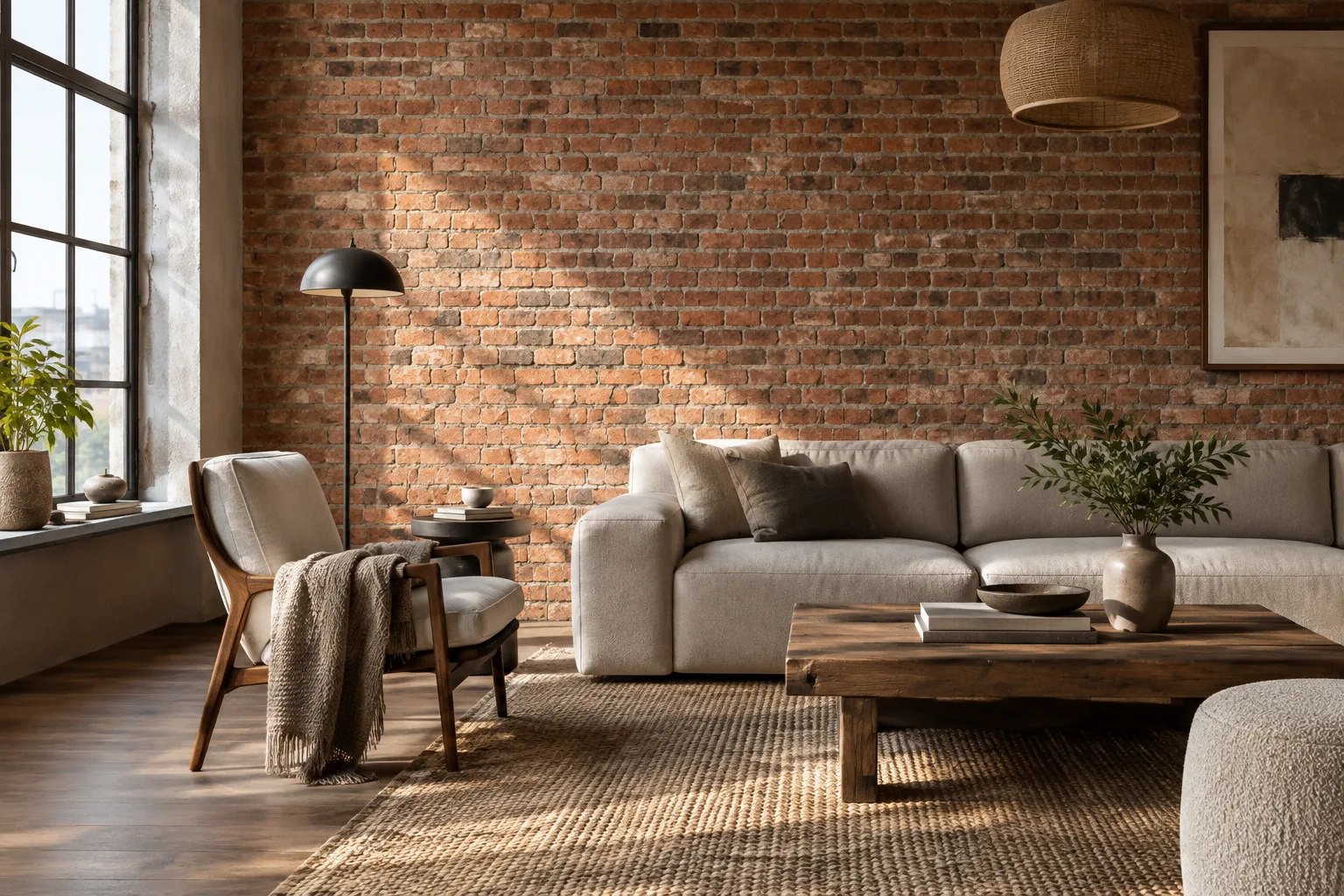
A procedural brick pattern can help architects, interior designers, and visualization artists who want to change colors, joints, and row patterns in facade and interior visualizations. Instead of modeling each brick individually, you can adjust the texture inputs to try out different surface looks. Mapping can be used when you need to adjust texture coordinates separately in Shader Nodes.
Before starting a project, confirm which nodes belong to each context and whether the required nodes are available in your Blender setup. The sources provide no information about performance gains, hardware requirements, pricing, or licensing terms. Pay particular attention to whether texture detail exceeds sampling limits in close-up shots.
Next steps
Start with a simple pattern using color and basic proportion settings. Then test the mortar, row offset, and compression settings one at a time, observing the effect of each change. If you’re using Shader Nodes, compare the effect of coordinate transforms by changing the Mapping type. Finally, inspect the pattern at different viewing scales in the target scene and check whether the detail density is appropriate.
Sources and license
This content has been adapted into Turkish based on the Brick Texture page in the Blender Manual and the Blender 4.0 Manual page for the Mapping node. Both sources are licensed under CC BY-SA 4.0.
Sources
2 sourcesSource texts are not republished; short quotes are marked, everything else is our own summary and commentary.
Brick Texture’s separate controls for color, mortar, and row settings offer a practical starting point for quickly testing surfaces in facade and interior visualizations. Keeping in mind that Mapping is described in the Shader Nodes context will help you set up the node workflow correctly when applying the method to a project.
The sources don’t provide enough cost information for offices and students in Turkey to make purchasing or hardware decisions. A more cautious approach is to first test the node behavior and visual result in your existing Blender setup. Be sure to check for moiré and loss of detail, especially with fine patterns.
Frequently asked questions
What does Blender’s Brick Texture node do?
It generates a procedural brick texture. You can adjust properties such as brick colors, mortar color, and pattern dimensions.
Is the Mapping node used in Geometry Nodes?
The source documents Mapping as a Shader Nodes node. This guide doesn’t show it being used in the same workflow as Brick Texture in Geometry Nodes.
What is the Factor output on the Brick Texture node?
It’s a mortar mask. According to the manual, a value of 1 represents the mortar area.