In brief
- Curve to Mesh converts curve splines into mesh geometry; without a profile, the result consists of chains of edges.
- The Profile Curve input defines the cross-section carried along the curve; Scale adjusts the profile at points on the curve.
- Fill Caps can close the ends of closed profile splines with n-gons.
- Miter Scale and Limit control how much the profile extends at sharp turns and set the maximum extension.
What will you learn in this guide?
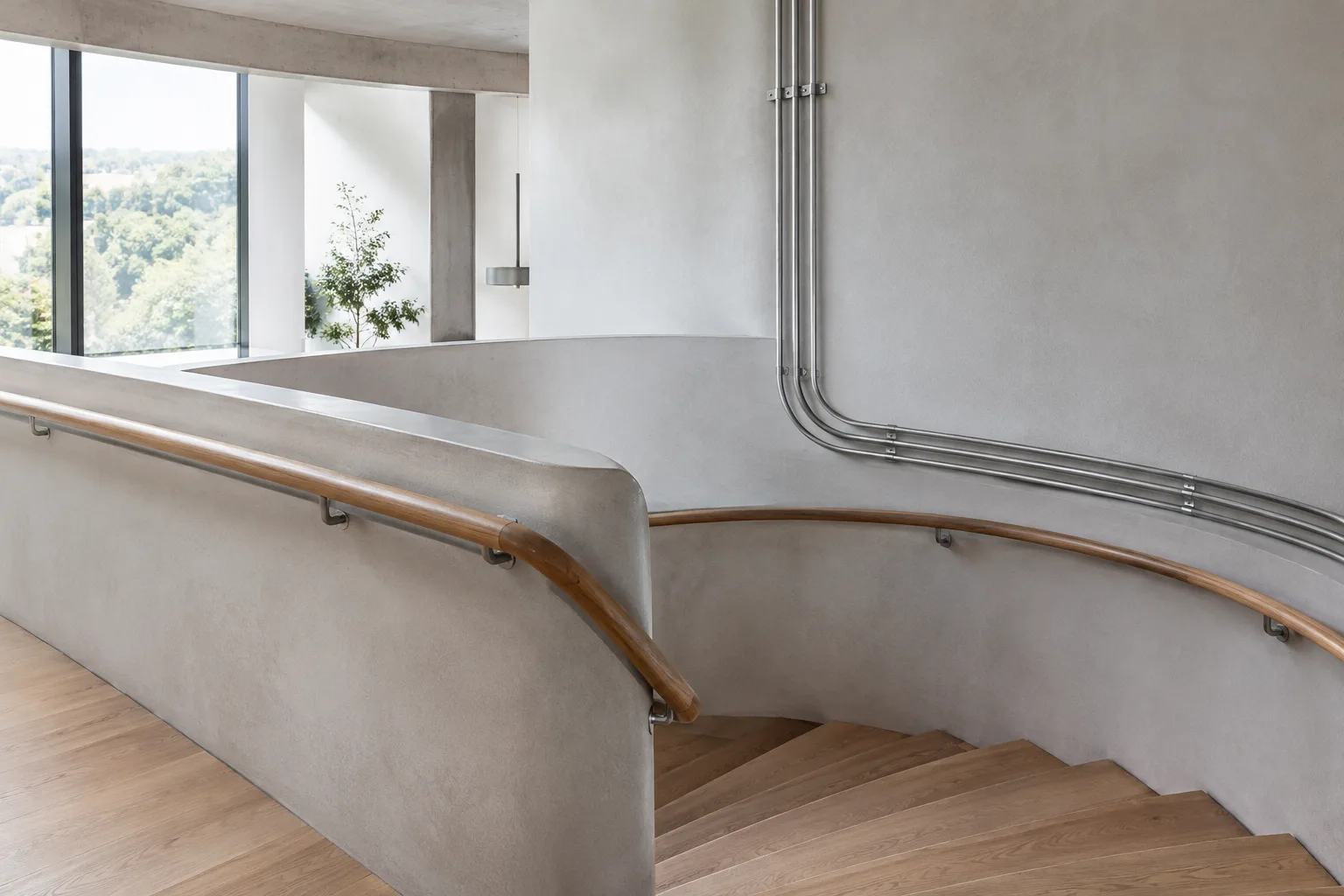
Blender’s Curve to Mesh node converts the splines of curve geometry into a mesh. In this guide, you’ll learn about the node’s main inputs and output, how a profile cross-section is carried along the curve, when the ends can be capped, and how to control sharp corners. This is useful when building forms that follow a curve in Geometry Nodes for architectural modeling, such as railings, pipes, cables, skirting boards, or façade elements. These are examples of possible uses; the node itself is not designed for any particular architectural object.
The key distinction is this: without a Profile Curve connected, Curve to Mesh does not turn splines into a surface or a volume with a cross-section. Instead, it outputs each spline as a chain of edges. To create a mesh with a cross-section, you also need to provide a profile curve.
Requirements and how the node works
The Blender manual used as the source explains the node in the Geometry Nodes section and presents the page as the “latest” manual; it does not provide compatibility information for a specific Blender version. Therefore, this guide does not specify a particular version requirement. For the node to work, provide curve geometry to the Curve input and, if you need a cross-section, a profile curve to the Profile Curve input.
The node’s main inputs and output are:
Curve: The curve geometry to convert to a mesh. Non-curve components are ignored.
Profile Curve: Defines the cross-section carried along the splines in the input curve. If left unconnected, the output is a chain of edges for each spline.
Scale: Scales the profile at points on the input curve.
Fill Caps: Can fill the ends of the generated mesh with n-gons if the relevant profile spline is closed.
Miter Scale and Limit: Define how the profile is scaled at sharp turns in the input curve and set the upper limit for that scaling.
Mesh: The output for the generated mesh geometry.
According to the manual, attributes from the input curves are transferred to the resulting mesh. Some mesh-specific attributes that are not present on the curve can also be transferred to suitable mesh domains. This means that not only the shape, but also existing attributes, can be preserved during the conversion.
Step by step: Create a profile with Curve to Mesh
Choose the curve to convert. Provide the curve geometry to use at the Curve input. Keep in mind that this node does not process non-curve components. If there are multiple splines, the node converts them to a mesh.
Decide whether you need a cross-section. If the result should be only a chain of edges, you can leave the Profile Curve input unconnected. If you want a form with a cross-section, such as a pipe or railing, provide a profile curve at this input. The profile describes the cross-section carried along each spline of the input curve.
Set the profile scale. The Scale input scales the profile at points on the input curve. For example, if you want to vary an element’s thickness along its path, check where the scale values change. The manual describes the Scale input’s behavior in these terms; it does not provide specific values or recommended dimensions for a project. Set the scale values according to the actual design dimensions.
Check miter behavior at sharp turns. The profile may extend as it follows the curve around sharp turns. Miter Scale controls the profile scale at these turns; according to the manual, the goal is to help keep the apparent width at corners more consistent. Check the resulting geometry, especially at tight turns.
Set a limit on the extension. Limit restricts how much miter scaling can increase at sharp corners. When the corner angle reaches the defined limit, the scale stops increasing. This can prevent the geometry from extending excessively at very sharp turns. If the turn angle varies in your design, check the corners as well as the straight sections.
Decide whether to cap the ends. When the relevant profile spline is closed, the Fill Caps option fills the ends of the generated mesh with n-gons. The manual notes that the caps are directly connected to the boundary edges and that the resulting mesh is manifold. If the profile spline is not closed, this condition is not met, so don’t assume the ends will be capped.
Inspect the mesh output. Check the generated geometry at the Mesh output: Is the profile connected? Is the cross-section oriented as expected? Are the ends capped, and are the corner areas acceptable? If there are unwanted extensions, review the Miter Scale and Limit settings. If the output looks different than expected when no profile is connected, remember that it consists of chains of edges.
What does it offer for architectural, interior, and archviz workflows?
This node can be useful in modeling workflows where you need to create an element with a repeating cross-section along a curved path. For example, a railing profile, cable, or skirting board can be built with the curved path and cross-section treated as separate inputs. This approach lets you consider the path and profile independently; it does not, however, mean that scene dimensions, materials, or compatibility with specific software are handled automatically.
For architectural presentation and archviz, corner quality is particularly important. An element that looks smooth along long, straight sections may extend excessively at tight turns. For this reason, check miter settings and end caps at corners that will be seen up close by the camera. The manual does not provide information on performance, hardware requirements, licensing terms, or transfer to other software, so no assumptions should be made on those topics. If the mesh output will be used in production or for delivery, verify separately that it meets the project requirements.
Common mistakes
Expecting a cross-section without a profile: Without a profile, the result is a chain of edges for each spline; no mesh with a cross-section is created.
Expecting caps on an open profile: Fill Caps depends on the relevant profile spline being closed.
Not checking sharp corners: Miter scaling can extend the profile at corners. Limit restricts this increase; inspect tight turns visually, in particular.
Overlooking non-curve components: Non-curve components at the Curve input are ignored. If the expected geometry is missing, check the input type.
Expecting sharp-edge marks on every profile: The manual specifies a particular condition for automatic sharp-edge generation: the profile spline must be Bézier, and at least one of its control points must use a Free or Vector handle. Don’t assume the same marking will occur if this condition is not met.
Next steps
Start by testing the basic conversion with a simple curve and a closed profile. Then change the Scale and Fill Caps behavior separately and compare the results. Finally, add sharp turns and examine the effects of Miter Scale and Limit. If the profile uses a Bézier spline with Free or Vector handles on its control points, also check whether the resulting edges are marked sharp. These tests can help you see where the node works for your project geometry and where additional adjustments are needed.
Source and license
This guide is adapted into Turkish from the “Curve to Mesh Node” page in the Blender Manual. The source page is licensed under CC BY-SA 4.0; the content has been adapted under that license. The explanations of curve and profile inputs, scale, caps, miter settings, and attribute transfer are based on information in the Blender manual.
Sources
1 sourceSource texts are not republished; short quotes are marked, everything else is our own summary and commentary.
Curve to Mesh offers a straightforward tool for modeling teams looking to build architectural elements that follow a curve parametrically. Treating the path and cross-section separately can provide flexibility when designs change; however, you need to connect a profile to get geometry with a cross-section and set the conditions for caps correctly.
For offices and students in Turkey, the key consideration is not so much the cost of trying the tool as whether the model meets delivery standards and how much attention the corners need. The source provides no information about hardware, licensing, or export compatibility, so it’s worth verifying the workflow with the version and delivery format you use before integrating it into production.
Frequently asked questions
What does Blender’s Curve to Mesh node produce without a profile?
Without a profile, each spline is converted into a chain of edges. To create a mesh with a cross-section, use the Profile Curve input.
How do you cap the ends of a mesh with Curve to Mesh?
When the relevant profile spline is closed, the Fill Caps option can fill the ends with n-gons. According to the manual, the caps connect to the boundary edges and the result is manifold.
How do you control sharp corners in Blender’s Curve to Mesh node?
Miter Scale controls profile scaling at sharp turns, while Limit restricts how much the scale can increase.