In brief
- With a perspective camera, a longer focal length narrows the field of view; a shorter one brings more of the scene into the frame.
- Lens shift helps adjust vanishing points without rotating the camera.
- A render region defined in Camera View also limits the final render.
- Wide clipping ranges can reduce depth precision in the 3D Viewport and cause visual artifacts.
Blender’s official camera and viewport documentation describes tools for managing framing, perspective, focus, and preview times in architectural visualization. The steps below bring together camera setup and troubleshooting for interior and exterior scenes. Since the documentation does not specify which Blender version applies, menu names and features are presented as they appear in the current source documentation.
1. Choose a camera type suited to the scene
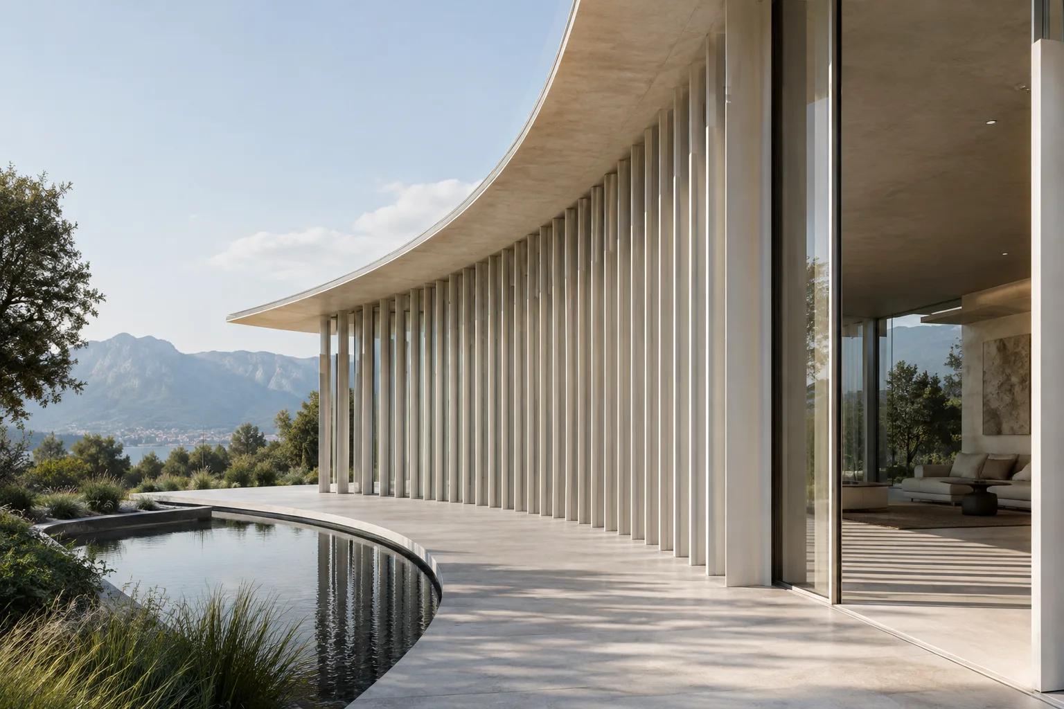
After making the camera the active object, review the lens options under Properties › Camera. Perspective view resembles how we see the real world: distant objects appear smaller, and parallel lines converge as they recede. Use it to create a sense of depth in an interior or to present an exterior with perspective.
Adjust Focal Length to suit the framing in a perspective camera. According to the official manual, a longer focal length narrows the field of view (FOV), while a shorter one shows a wider area. So, when you need a wider frame, consider adjusting focal length rather than having to move the camera closer to the scene. The documentation does not recommend a specific numerical value for architectural shots, however, so test the framing in your scene.
Consider Orthographic when you want to avoid parallel lines converging, such as in drawings and presentations. In this view, objects appear at their true size regardless of distance, and parallel lines do not converge. Orthographic Scale determines the size of objects in the image; the documentation notes that this is the only setting that affects orthographic view.
| Setting | Recommended value | Effect |
|---|---|---|
| Perspective focal length | The manual does not recommend a fixed value | A longer focal length gives a narrower FOV; a shorter one gives a wider FOV. |
| Orthographic Scale | Adjust to suit the framing | Determines the size of the area shown in orthographic view. |
| F-Stop | The manual does not recommend a fixed value | A lower value produces a stronger depth-of-field blur. |
2. Control verticals and framing with lens shift
Use the Shift setting to adjust vanishing points in perspective view. The manual specifically emphasizes that lens shift produces a different result from rotating the camera: with shift, horizontal lines remain horizontal, whereas rotating the camera can make them tilt. Keep this distinction in mind when you need to control vertical and horizontal lines in architectural elevations or interior perspectives.
Use Sensor Fit to determine how the sensor fits the output dimensions. Auto calculates a square sensor size based on the larger dimension of the resolution. Horizontal lets you set the width manually and calculates the height according to the output aspect ratio; Vertical lets you set the height manually and calculates the width to match the ratio. Sensor size is also an alternative way to control the field of view when matching a real camera-and-lens combination.
If objects are missing from the scene, first check the camera’s Clip Start and Clip End range. The camera does not show objects outside this range. Very wide clipping ranges can reduce depth precision in the 3D Viewport and cause artifacts. The documentation’s troubleshooting suggestions for large scenes are to increase the near clipping value and, if distant objects are not in the frame, reduce the far clipping value. To make the camera limits visible, use Show – Limits in the Viewport Display panel.
3. Use focus and depth of field with control
Set the plane of focus by choosing a Focus Object or, without selecting an object, adjusting Focus Distance. When a focus object is assigned, the distance parameter is disabled. As you set where the camera view will be sharp, make sure these settings match the subject in the scene.
Instead of estimating the distance manually, try the Depth Picker method described in the manual. Hover over the Focal Distance property and press E, then click the point in the 3D Viewport from which to pick the distance using LMB. You can monitor the focus distance in the viewport using Viewport Display › Show – Limits.
Control the amount of blur with F-Stop. Lower values strengthen the depth-of-field effect. Use Blades to set the shape of the bokeh; Rotation controls the rotation of the blurred shape, while Ratio controls anamorphic-style distortion. The source does not provide numerical settings specifically for architectural visualization, so make the final choice based on the framing and the desired look.
4. Speed up previews and troubleshoot issues
When repeatedly checking only part of an image, use View › View Regions › Render Region or mark an area with Ctrl-B. Previewing the selected rectangle instead of the full image can save time when making small changes. A region defined in Camera View also applies to the final render; use Ctrl-Alt-B to clear it. A region defined outside Camera View affects only the viewport. Two render regions can exist at the same time. The documentation states that render regions work in the Cycles viewport but are not applied to the EEVEE viewport; they always affect the final render.
To view or edit only part of a complex model, draw a rectangle using View › View Regions › Clipping Region or Alt-B. This tool limits geometry in the 3D Viewport to the defined volume; geometry outside the visible area is also ignored by operations such as painting, sculpting, selection, and transformation. Press Alt-B again to turn the tool off. This is not the same as camera clipping distances: region clipping is for working in the viewport.
If the viewport is empty, select an object in the Outliner and focus on it with View › Frame Selected or NumpadPeriod; Home frames all objects in the viewport. If selection is slow, the manual lists updated graphics drivers, Wireframe view, or selecting from the object center with Ctrl in Object Mode as possible solutions. These are troubleshooting options, not general or guaranteed performance fixes.
Common mistakes
Setting the near and far clipping boundaries too far apart in a large scene, causing depth artifacts in the 3D Viewport.
Trying to straighten verticals by rotating the camera and tilting horizontal lines, while overlooking the different effect of lens shift.
Forgetting to clear a render region defined in Camera View and not realizing that it also limits the final render.
Expecting focal length to behave in Orthographic view as it does in a perspective camera; in this mode, framing size is controlled with Orthographic Scale.
Impact on architectural and visualization workflows
These tools are especially useful to architects, interior designers, and visualization artists working on interior framing, elevation presentations, and complex models. Choosing between perspective and orthographic views based on the purpose, controlling lines with lens shift, and rendering only the required area can help organize the iteration process. Those using EEVEE should account for the fact that render regions are not applied to the viewport, but do affect the final render. The sources do not specify costs, licensing terms, or hardware requirements; depth precision and graphics driver behavior are technical points to check in your own scene.
Sources
3 sourcesSource texts are not republished; short quotes are marked, everything else is our own summary and commentary.
For small and large offices in Turkey, the most practical benefit of this guide is being able to test framing and material changes in a small region without rendering the full frame. Lens shift is another often-overlooked control that helps adjust the presentation framing while keeping architectural lines straight.
Still, a render region does not eliminate hardware requirements on its own, and it affects the viewport differently in Cycles and EEVEE. In shared office files, checking camera clipping boundaries and the active render region can help prevent unexpected crops. Since the documentation does not specify version, licensing, or hardware requirements, these points should be verified in the setup being used.
Frequently asked questions
Should I use perspective or orthographic view for an architectural camera in Blender?
Perspective view creates a sense of distance and vanishing points. In orthographic view, objects appear at their true size regardless of distance, and parallel lines do not converge; the choice depends on the purpose of the presentation.
How do I clear a render region in Blender?
Use the Ctrl-Alt-B shortcut to clear a render region. Since a region created in Camera View also affects the final render, check it when you’re finished.
What should I do if Blender camera clipping boundaries cause artifacts?
For large scenes, the official manual recommends increasing the near clipping value and reducing the far clipping value if distant objects are not visible. If objects are missing from the camera view, also check whether the clipping range is too narrow.