In brief
- A mesh object can have multiple UV maps, and one map can also be used by multiple textures.
- The UV map marked Active Render is used for the UV Pass and in material shading.
- You can create a UV Grid or Color Grid image in Blender to check for UV distortion.
- Texture Space does not support rotation; use a Mapping Node to rotate coordinates in a material.
What will you learn in this guide?
Correctly placing textures on a model’s surface depends on setting up UV maps and image files together. In this guide, you’ll learn how to find a mesh object’s UV maps in Blender, choose the map used for rendering, and add a new map. We’ll then cover Texture Space, which generates texture coordinates without using a UV map, along with test images and the basic image settings.
This guide is limited to functions described in Blender’s official manuals. It does not cover UV unwrapping or methods for editing a model’s geometry; instead, it focuses on managing existing maps and checking how textures are used.
Requirements
You’ll need a Blender installation with access to the editors described in the official manual and a mesh object to work on. UV maps are listed in the UV Maps panel under the Data tab of the Properties editor, while image options are found in the image settings. You can view and edit a map in the UV Editor. The sources do not specify any special account, add-on, or hardware requirements.
The manual pages referenced here are from the “latest” version of the Blender Manual; no specific Blender version number is given. If option names or their locations look different in your interface, it may be helpful to check the manual for the version you’re using.
Step-by-step: Setting up a UV map
Select the mesh object. Go to the Data tab in the Properties editor. The selected mesh object’s UV maps are listed in the UV Maps panel on this tab.
Inspect the map you want to use. After selecting a UV map from the list, you can view and edit it in the UV Editor. A single mesh can have multiple UV maps. For example, you can keep separate maps for different textures, or use the same map for multiple textures.
Set the active map for rendering. Mark the map you want to use as Active Render. Blender uses this map for the UV Pass in compositing and for the UV output of the Texture Coordinate Node in material shading. The Active Render map is also used if a material contains a UV Map Node without a specific map name selected. So, if a file contains multiple UV maps, check this setting to ensure the render uses the expected map.
Add or remove a map. If a map is selected in the list, Add UV Map duplicates it; if the list is empty, it creates a new map. Remove UV Map deletes the selected map. Before removing one, check whether it is used in materials or the render workflow.
Consider using Texture Space if needed. Texture Space is a three-dimensional box used to generate texture coordinates without a UV map. You can calculate it automatically using Auto Texture Space in the Texture Space panel under the mesh object’s Data tab. You can also adjust the Location and Size values manually along the X, Y, and Z axes. To display the box in the viewport, use the option in the Viewport Display panel.
Edit Texture Space in the viewport. The manual describes adjusting its position or size using Object > Transform > Move/Scale Texture Space in Object Mode. After starting the operation, move the mouse and confirm with a left-click. You can use keyboard shortcuts to lock the axes during a transform; the applicable shortcuts are shown in the status bar.
Texture Space does not support rotation. If you need to rotate coordinates in material shading, the method described in the manual is to pass the Generated coordinates from a Texture Coordinate Node through a Mapping Node. The Generated output provides three-dimensional coordinates within the object’s Texture Space, which you can connect to a texture node.
Setting up images and test textures
In the image settings, you can choose the source type: Single Image uses one still image, Image Sequence uses an animation made up of frames in separate files, and Movie uses a video file. For video sources, Blender plays back at the scene’s frame rate; if that rate does not match the video, playback speed may differ from what you expect. These options are for previewing; to adjust the 3D Viewport or render result, use the options in the Image Texture Node.
You can use a test image generated in Blender to check UV placement:
Select Generated as the image source.
Set the image’s width and height in pixels using the X and Y fields.
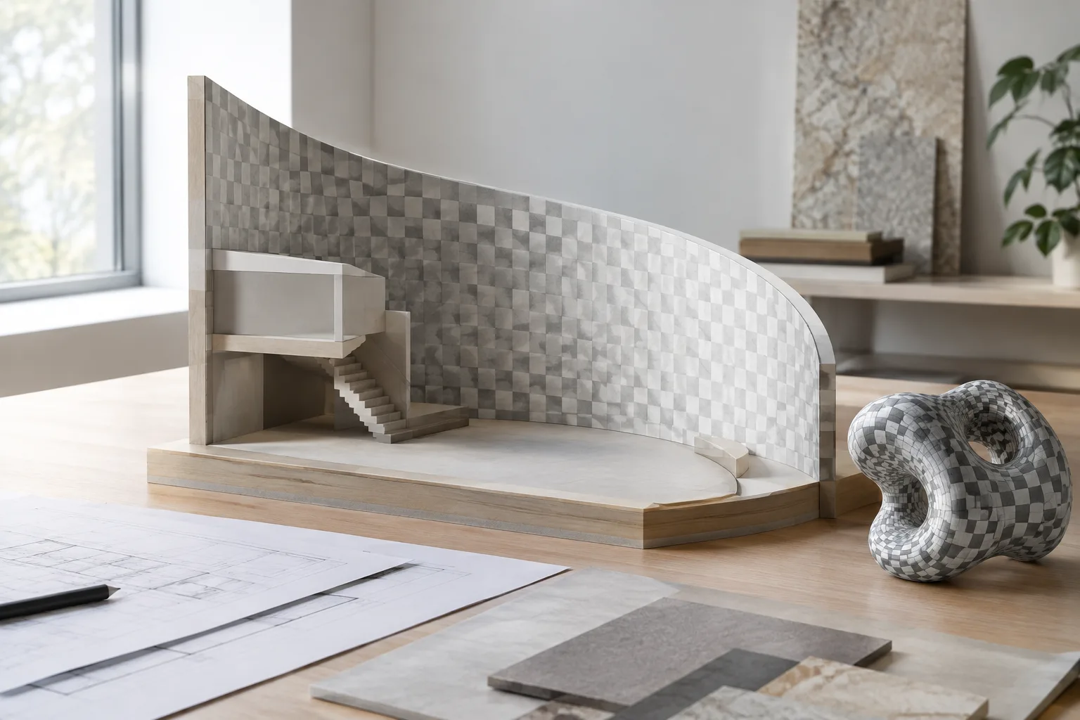
Choose UV Grid or Color Grid from the Type menu. UV Grid creates a checkerboard pattern with colored plus signs in the squares; Color Grid creates a more detailed grid with letters and numbers indicating position. According to the manual, Color Grid can be used to check for stretching or distortion in UV mapping.
Inspect how the texture looks on the model and how it is laid out in the UV Editor. If the grid stretches or changes shape unexpectedly, review the UV layout.
The texture file’s color space is important too. Blender uses the color space in which the image was saved to convert the data into its own linear color space. Maps that do not carry direct color information, such as normal, bump, or stencil maps, should not undergo color conversion; select Non-Color for these images. The available color spaces depend on the active OCIO configuration.
Common mistakes and next steps
If you don’t check the Active Render setting when there are multiple UV maps, the render or material may not use the expected map. It can also be confusing to think of Texture Space as a UV map: one uses a three-dimensional box to generate coordinates without a UV map, while the other is a UV map for the mesh. Also, trying to rotate Texture Space directly won’t work; if you need rotation, adjust the coordinates in the material using a Mapping Node.
Don’t confuse preview settings with render settings. The frame and playback options described for video are for previewing; for rendering and the 3D Viewport, check the Image Texture Node options. In Texture Paint Mode, a fixed edge margin is used, while the Seam Margin setting only takes effect in Sculpt Mode; texture painting support in this mode is described as experimental in the manual. A higher Seam Margin produces a thicker margin and can be useful when using mipmaps, but may reduce painting performance.
As a next step, check the map names used in materials, the Active Render setting, and the images’ color spaces together. If you’re moving texture files along with the project, the Pack option embeds the source in the current blend file. Especially when handing files over within a team, confirming how maps and image sources are stored makes the workflow more predictable.
Sources and license
This guide has been adapted into Turkish from the “UVs & Texture Space” and “Image Settings” pages in the Blender Manual. Both sources are published under the CC BY-SA 4.0 license.
Sources
2 sourcesSource texts are not republished; short quotes are marked, everything else is our own summary and commentary.
This workflow is most useful during the checking stage for architecture students, visualization artists, and offices preparing materials and textures in Blender. Setting the Active Render map and using Color Grid to spot distortion can help catch issues that might otherwise be missed before delivery.
The sources do not specify any special hardware or paid add-ons, but keep in mind that the interface in the manual may not match the Blender version used in your office. Distinguishing the different roles of Texture Space and UV maps, and using Non-Color for maps that do not carry color data, are practical checkpoints for consistent results across scenes.
Frequently asked questions
What does the Active Render UV map do in Blender?
The map marked Active Render is used for the UV Pass in compositing and in material shading. A UV Map Node with no specific map selected also uses this map.
How can I check for UV distortion in Blender?
Create an image with the Generated source and select UV Grid or Color Grid. Color Grid can be used to check for stretching and distortion in UV mapping.
Which color space should I use for a normal map in Blender?
Maps such as normal, bump, and stencil maps should not undergo color conversion. Select Non-Color for these images.