In brief
- For walls to join, it's not their bodies but their reference lines that must intersect or touch each other.
- Layer Intersection Number can prevent walls on different layers from intersecting; if both walls are in group 0, no connection forms.
- At corners where three or more walls of equal priority meet, Junction Order determines which pair joins first.
- In composite walls, correct intersection of skins depends on the Intersection Priority value in the Building Materials panel; a higher-priority material cuts through a lower-priority one.
One of the most common modeling issues in Archicad projects is when two walls visually overlap but fail to form a clean junction at the corner. According to Graphisoft's official help documentation, this isn't usually due to a single cause but rather the interplay of four separate settings: reference line, layer intersection number, junction order, and priority-based connection in composite walls. This guide, based on official documentation for Archicad 25 and 29, walks through these four settings in practice.
Why aren't the walls joining?
In Archicad, even if wall bodies overlap, what truly determines the junction is the wall's invisible Reference Line property. This line is hidden by default; it appears blue when the wall is selected, and as a black line with an arrow when View › On-Screen View Options › Walls & Beams Reference Lines is enabled. The arrow indicates the wall's drawing direction.
According to the documentation, overlapping alone isn't enough for a proper junction — the reference lines must touch or intersect each other. The Auto-Intersect function is enabled by default and automatically extends the reference lines of overlapping walls to join them; this feature can be toggled from the Options menu. To intersect two existing elements with a single click, you can select them and use the Intersect command.
Step by step: Settings for correct wall junctions
Check the reference line. Enable
View › On-Screen View Options › Walls & Beams Reference Linesto confirm that the walls' lines actually intersect.Set the layer intersection number. Assign walls you don't want connected to layers with different
Layer Intersection Numbervalues. Elements in the same group (same number) join if their geometry is correct; if both elements are in group 0, they will never join. This setting is found underDocument › Layers › Layer Settings(Ctrl+L).Use Junction Order at corners where three or more walls meet. When three or more walls of equal priority intersect at a point,
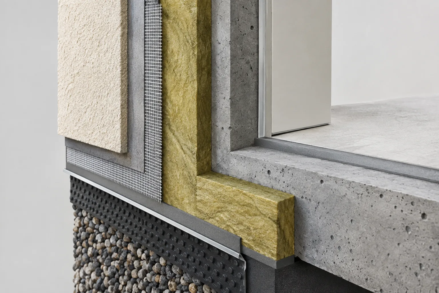
Junction Orderdetermines which pair joins first; a higher order number takes priority. This value is set in the Model panel of the Wall Settings dialog.Apply Priority Based Connection (PBC) in composite walls. In composite walls, it's not enough for just the wall bodies to join — skins such as insulation and concrete must also intersect in the correct order. This depends on the
Intersection Priorityvalue defined underOptions › Element Attributes › Building Materials; a higher-priority building material cuts through a lower-priority one.
| Setting | Location | Effect |
|---|---|---|
| Reference Line / Auto-Intersect | Options menu, View On-Screen View Options | Determines whether walls visually join |
| Layer Intersection Number | Document › Layers › Layer Settings | Prevents or allows intersection of walls on different layers |
| Junction Order | Wall Settings › Model panel | Determines join order at corners where 3+ walls meet |
| Intersection Priority (PBC) | Options › Element Attributes › Building Materials | Determines which composite wall skin cuts through which |
Skin order and core setting in composite walls
In Archicad, a composite building element can have up to 48 skins defined. Skins are separated from each other by a separator line, while the outer boundary is called the contour line. Composite elements can include one or more structural skins designated as Core, though defining a Core skin is not mandatory. Skins designated as Core and Finish also affect Partial Structure Display views. These definitions are made under Options › Element Attributes › Composites, and the Use With control in the same menu determines which element types (Wall, Slab, Roof, Shell) the selected composite can be used with.
Why do these settings matter for architecture firms?
Correctly configuring intersection and priority settings is critical, especially for multi-layer exterior walls (insulation + structural + cladding), to ensure corner details are calculated accurately. If the insulation layer isn't cut correctly at a corner in section drawings, it can distort both quantity takeoffs and visualization outputs (3D renders, Partial Structure Display views). For this reason, standardizing Building Materials priority values in the office template at the start of a project reduces repetitive correction work later on.
Common mistakes
Noticing that wall bodies overlap but not checking whether the reference lines actually intersect.
Keeping all walls on the same layer and never using Layer Intersection Number, which leads to unwanted joins.
Leaving Intersection Priority values at default in Building Materials for composite walls, allowing skins to intersect randomly.
Expecting correct results automatically at three-wall corners without setting Junction Order at all.
Sources
3 sourcesSource texts are not republished; short quotes are marked, everything else is our own summary and commentary.
In offices using Archicad, wall junction issues are usually not modeling errors but missing settings. When reference line, layer intersection number, junction order, and priority-based connection aren't considered together, section and quantity errors can emerge, especially in multi-layer façade systems.
Building these four settings into the office template from the start significantly reduces repetitive correction work as a project progresses. For teams working with composite walls in particular, reviewing the priority values in the Building Materials panel at the start of a project saves time during both documentation and visualization stages.
Frequently asked questions
Why won't two walls join in Archicad?
Even if the wall bodies overlap, a junction requires that the reference lines intersect or touch each other; walls with different Layer Intersection Number values also won't join.
What does Layer Intersection Number 0 mean?
Two elements that are both in intersection group 0 will not connect to each other, even if their geometry is correct.
How many skins can a composite wall element have at most?
According to Graphisoft documentation, a composite building element can contain up to 48 skins.