In brief
- Patch can create a surface from selected curves, meshes, point objects, and point clouds.
- Loft creates a surface through profile curves selected in sequence.
- DevLoft creates a single surface between two curves that can be flattened with UnrollSrf.
- A Patch surface may not pass exactly through all input curves; DevLoft also does not guarantee that the result can be fabricated.
In Rhino 8, the Patch, Loft, and DevLoft commands can be used to create forms from different types of curve and surface input. McNeel’s Rhino 8 documentation explains that Patch works with curves, meshes, point objects, and point clouds; Loft creates a surface from profile curves; and DevLoft creates a single developable surface between two curves. Choose a command based on how the target geometry is defined and how the surface will be used downstream.
1. Create a surface from curves and points with Patch
Patch creates a surface from selected curves, edges, meshes, point objects, and point clouds. The command first finds the best-fit plane among the selected and sampled points, then deforms that plane to fit the inputs. Patch therefore offers an approach to surface creation supported by varied inputs, rather than defining the form primarily with a few section profiles.
After running the command, select the surface constraints and set the options. Sample point spacing defines the physical spacing between sample points along an input curve; according to the documentation, each curve has at least eight sample points. Surface U spans and Surface V spans set the number of U and V spans in the automatically generated surface. These values are also used when the starting surface is a 1x1-span plane.
Stiffness controls how much the best-fit plane deforms to match the inputs. Higher values keep the surface stiffer, more rectangular, and more planar. The documentation suggests trying small values or values greater than 1000; this does not mean there is one recommended value. Check the result with Preview. After changing an option, press the button again to refresh the preview.
If you want to use an existing surface, select a similarly shaped starting surface with Select starting surface. Starting surface pull controls how closely the new form follows this starting surface; higher values pull the result closer to its original shape. Preserve edges keeps the starting surface’s edges fixed. Use Adjust tangency when tangency to the edges of an existing surface is required. Automatic trim attempts to find the outer boundary and trim the surface. To create a closed trimmed patch, select the boundary curves in an order that makes them touch end to end.
2. Turn profile curves into a surface with Loft
Loft passes through the profile curves that define the path of the surface. Select the curves in the order the surface should follow. For open curves, select them near the same ends; for closed curves, align the seams. On closed curves, Flip reverses the curve direction, while Automatic attempts to align seam points and directions automatically. When adjusting seam points manually, make sure they are aligned and that the direction arrows point the same way.
The Style option affects the surface shape. Loose is intended to preserve the relationship between the surface control points and their original positions; the documentation considers this option suitable when the control points will be edited later. Normal applies an average amount of stretching between curves. Straight sections creates straight sections between curves. Tight fits the surface more closely to the original curves and may be considered when profiles pass around a corner. Closed loft closes the surface when three shape curves are selected.
If the start or end curve is an edge of an existing surface, Match start tangent and Match end tangent help preserve tangency to the adjoining surface. If some ends of the Loft profiles touch while others do not, the command restricts the style to Straight sections to prevent self-intersecting loops. Treat this behavior as a constraint to check if the surface shape is unexpected.
3. Consider DevLoft when a flattened surface is the goal
DevLoft creates a single developable surface between two curves. Select the curves near the same ends. The resulting surface can be flattened with the UnrollSrf command. This makes DevLoft worth considering for work where a planar development of the form needs to be examined; however, the command alone does not guarantee that the result is suitable for fabrication.
For finer control, use the interactive mode by adding a hyphen to the command name: -DevLoft. Density specifies the number of rulings created across the surface. Use AddRuling to add rulings that define straight sections on the surface; the preview updates when you select points on the two curves for the added ruling. Untwist attempts to improve the rulings, and running it more than once may help. CurvatureDisplay visualizes the surface’s Gaussian curvature using false colors. The documentation notes that blue areas indicate where stretching or compression distortion occurs during flattening.
| Setting | Suggested value | Effect |
|---|---|---|
| Patch: sample points per curve | At least 8 | The minimum sampling requirement in the documentation. |
| Patch: Stiffness | No single value is specified; preview different values. | Higher values make the surface stiffer, more rectangular, and more planar. |
| Patch: Starting surface pull | No single value is specified. | Higher values pull the result closer to the starting surface. |
What should you consider in an architectural visualization workflow?
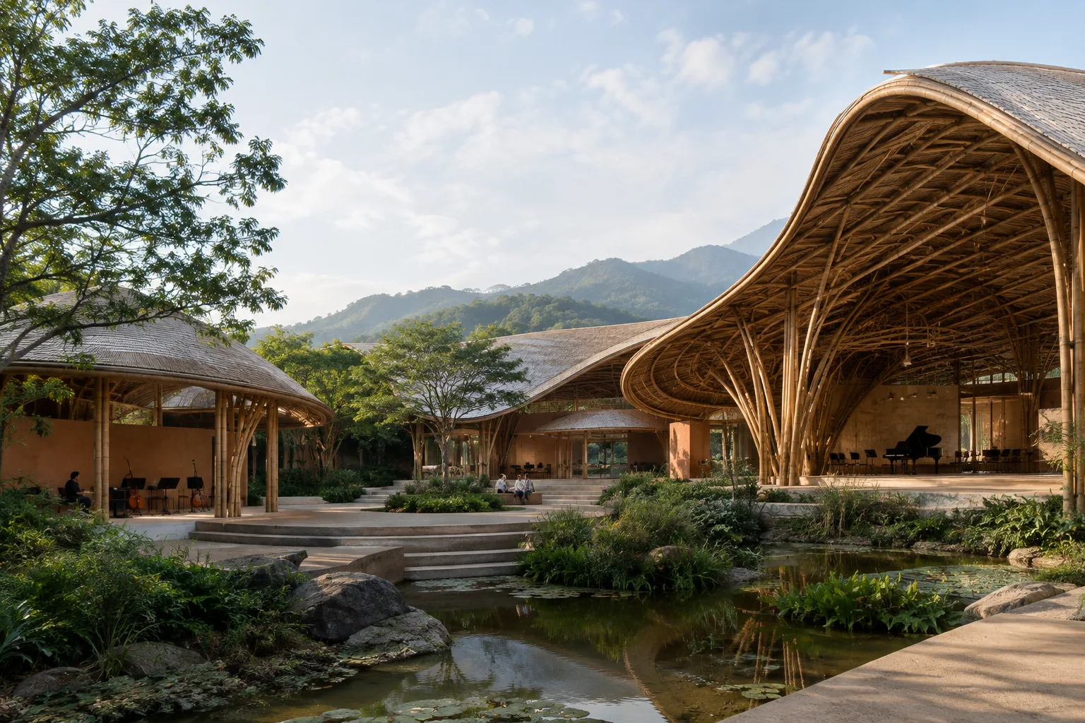
For curved façades, shells, or custom-shaped surfaces, choose a method based on the geometry you have: consider Patch when you have many input curves and points, Loft when you have ordered section profiles, and DevLoft when you need a developable surface between two curves. These commands rely on different shaping methods, so producing the same geometry with each one does not mean the results will be equivalent.
When working in Rhino 8, keep in mind that Patch may not pass exactly through the curves and that the manufacturability of a DevLoft surface is not guaranteed. With Loft, check the seams and directions of closed profiles; with Patch, check the preview and starting surface options. The documentation does not specify hardware requirements, licensing terms, or a separate compatibility restriction for these commands; do not make assumptions about these topics.
Common mistakes
Assuming Patch will pass exactly through every input curve. According to the documentation, the surface may not pass exactly through all the curves.
Failing to refresh the
Previewafter changing an option.Selecting Loft curves in an arbitrary order or failing to check the seams and directions of closed curves.
Assuming a DevLoft result is confirmed to be manufacturable. The documentation makes no such guarantee.
Not trying another approach when Patch does not produce a suitable result. McNeel suggests trying the
Sweep2command in this case.
Sources
2 sourcesSource texts are not republished; short quotes are marked, everything else is our own summary and commentary.
For architecture and visualization teams in Turkey, the practical value of these commands lies in being able to handle different geometry definitions with the right tool. Section curves offer a more suitable starting point for Loft, scattered reference inputs for Patch, and the need to develop a surface between two curves for DevLoft. This can reduce the risk of proceeding with the wrong command during trial and error.
Still, a quick preview is not a guarantee of fabrication suitability or a flawless surface. For work intended for manufacturing, in particular, consider DevLoft’s limitation and the fact that Patch may not pass exactly through its inputs. The documentation provides no hardware, pricing, or licensing information for these commands; offices should validate them against their own Rhino 8 installations and project requirements.
Frequently asked questions
What does the Patch command do in Rhino 8?
Patch creates a surface from selected curves, meshes, point objects, and point clouds. The surface may not pass exactly through all input curves.
What should you check when creating a Loft surface from closed curves in Rhino?
Align the seam points and directions of closed curves. Loft options let you try automatic seam alignment or reverse a curve’s direction.
Can a Rhino DevLoft surface be flattened?
DevLoft creates a single developable surface between two curves, and the result can be flattened with `UnrollSrf`. However, the documentation does not guarantee that the surface will be manufacturable.