In brief
- Curve to Tube generates a cylindrical or custom-profile mesh along a curve.
- Sample Curve returns position and direction data at a specific distance along a curve or at a specified fraction of its length.
- Instance on Points repeats an element by adding geometry references to selected points.
- Spline Parameter extracts length and factor information for control points along a curve.
What will you learn in this tutorial?
This tutorial covers turning curves into geometry in Blender Geometry Nodes for use in architectural visualization. First, we’ll look at the Curve to Tube node, which creates a pipe or cable along a curve. Then we’ll use Sample Curve to get position and direction data from specific points on a curve, and Spline Parameter to read progress along the curve. Finally, we’ll use Instance on Points to place geometry repeatedly at points.
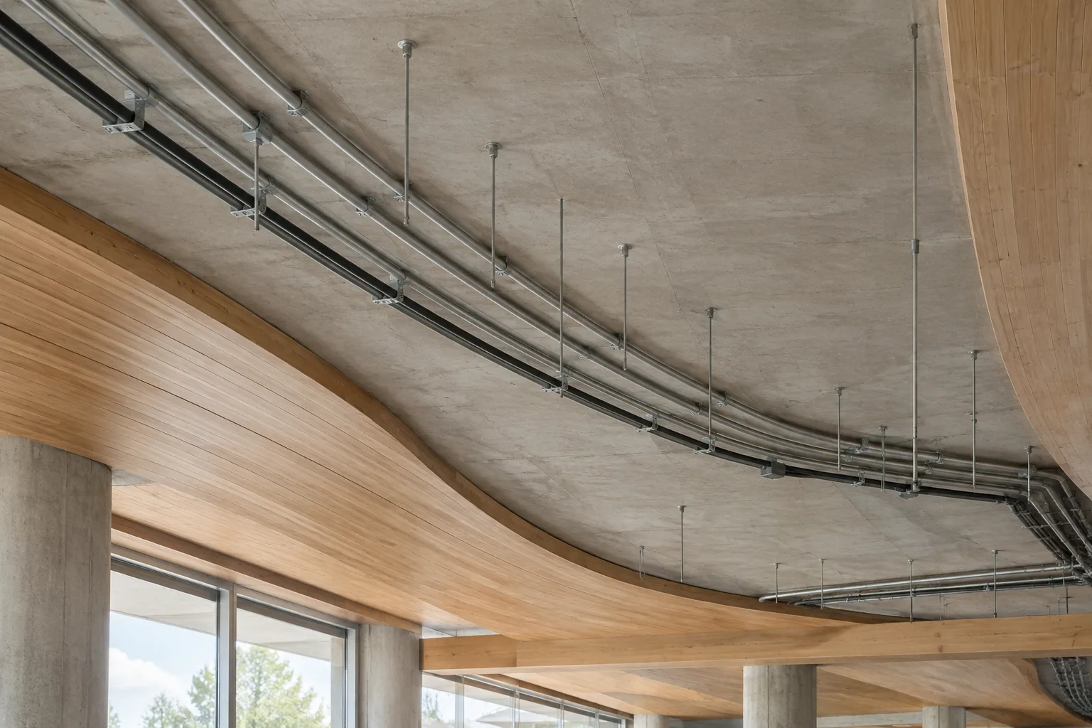
These techniques can be useful for visible cable and pipe runs in an interior, repeating elements on a facade, or fixtures repeated throughout a scene. Before using the results in a construction project, verify them separately against the project’s dimensions, connections, and fabrication requirements.
Requirements and preparation
You’ll need Blender and Geometry Nodes. The source documentation does not specify a particular Blender version, account requirement, or hardware requirement. For that reason, we won’t provide version-specific menu paths or steps; we’ll focus on the documented functions of the nodes.
Before you begin, create a curve in your scene or prepare the curve geometry you plan to use. Curve to Tube takes a curve as input. Instance on Points requires geometry that contains points: this can be a mesh, a point cloud, or a curve with control points. Decide in advance what the curves and points represent in your scene to make the node setup easier to understand.
Step-by-step workflow
1. Turn a curve into pipe or cable geometry
Connect the curve you want to use as a path to the Curve to Tube node. The node generates a mesh tube that follows the curve’s shape. The Round option creates a circular profile; Custom lets you use a custom object or geometry as the profile.
The Scale value on the node determines the tube’s radius by multiplying the curve’s radius attribute. So, when assessing the result, consider not only the Scale value but also the radius information on the input curve. If you need smooth shading, you can enable Shade Smooth.
2. Adjust geometry density and end caps along the curve
How smoothly the tube follows the curve is related to the sampling settings. In the Resample section, you can choose Evaluated, Auto, Count, or Length. Count uses a fixed number of sample points, while Length sets the distance between samples; Auto calculates a sampling length based on the curve’s details. Compare these options according to your project’s needs, and note that the source documentation does not specify a single correct value for every scene.
You can use the Caps option to close the ends. Flat creates a single n-gon at the end; Round uses rounded cap geometry. Custom creates caps using custom geometry. The node can also create a UV map or modify an existing one. UV generation offers Factor, Length, and Index methods. If you want changes in the curve’s radius to be taken into account when calculating UVs, consider the Consider Curve Radius option.
3. Sample a specific position on a curve
Use the Sample Curve node when you need data for a particular position along a curve. You can define the sample location with Factor, as a fraction of the curve’s total length, or with Length, as a distance from the start. The node returns the sampled position as Position, the curve direction as Tangent, and the Normal. It also returns the value of the field provided to the Value input at the sample point.
These outputs can be used as point-position or direction data in another node setup. For example, the Tangent output can be used for an element that needs to align with the curve’s direction; the documentation also gives the Align Rotation to Vector node as an example for creating rotation from a direction vector. With curves that contain multiple splines, bear in mind that Factor and Length calculations may take the total curve length into account. The All Curves option on the node changes the scope of this behavior.
4. Read progress along a curve
The Spline Parameter node has no inputs; its outputs are Factor, Length, and Index. In the Point domain, Factor gives a control point’s fraction of the spline’s length, while Length gives the distance from the start of the spline to that point. You can use this information for a property that changes along the curve.
There’s an important detail to keep in mind: with Bézier and NURBS curves, the node returns values at control points, not at every visibly evaluated point. As a result, the output may not follow the curve’s expected appearance. If you need more control points, one of the methods suggested in the documentation is to create a poly spline with Resample Curve. Also note that when the curve has zero length, Factor is determined differently from the usual calculation.
5. Place geometry repeatedly at points
Connect geometry containing points to Points on the Instance on Points node, and the object or geometry to be repeated to the Instance input. Selection determines which points receive instances. The Rotation and Scale inputs control the orientation and size of the resulting instances.
When Pick Instances is enabled, the node places an item selected by Instance Index at each point, rather than using all the geometry from the Instance input at every point. This can be used together with the Collection Info node. If the input geometry already contains instances, new instances can be nested; the effect of parent instances is also taken into account in the transform. When you need to convert instanced elements into separate objects, you can use Make Instances Real.
Using these nodes in architectural and visualization workflows
Interior designers and visualization artists can use these nodes to turn curve paths into pipes, sample direction data along a path, or place the same geometry at points in a scene. Using instances is a way to add the same geometry to a scene many times instead of duplicating the data repeatedly. However, the sources do not provide information about specific performance gains, hardware requirements, or compatibility with other software.
At the end of the workflow, check the tube’s profile, end caps, UVs, and the orientation of repeated elements. When using a custom profile or variable radius in particular, inspect the visual result and geometry according to the project’s needs. These nodes assist with modeling and visualization; they do not replace separate verification of construction dimensions and technical suitability.
Common mistakes
The curve looks more angular than expected: Check the Resample method and sampling settings.
The pipe radius is not the intended size: Remember that Curve to Tube’s Scale value is multiplied by the curve’s radius attribute.
Values along the curve don’t match its visible shape: Keep in mind that Spline Parameter uses control points for Bézier and NURBS curves.
The instance orientation is wrong: Review the Rotation input on Instance on Points and the direction data you’re using.
The sample position is surprising on a curve with multiple splines: Bear in mind that Sample Curve’s length calculation may take spline order and total length into account.
Next steps
Start with a single curve and compare the result by changing the tube profile, sampling method, and caps. Then examine separately what data the Sample Curve and Spline Parameter outputs provide in your node setup. Finally, try combining point geometry and an instance input to create repeating elements. Check the scene geometry at every stage and compare the node output with the project’s dimensional and visual requirements.
Source and license
This tutorial is adapted from the Blender Manual documentation for Instance on Points, Sample Curve, Curve to Tube, and Spline Parameter. All four documents are published under the CC BY-SA 4.0 license; the content has been translated and adapted into Turkish.
Sources
3 sourcesSource texts are not republished; short quotes are marked, everything else is our own summary and commentary.
This group of nodes can help architecture offices and students in Turkey organize repetitive scene work. For cable runs, pipes, and similar curve-based elements in particular, using data and instancing instead of modeling each element individually can simplify the workflow.
Still, before starting, verify that the relevant nodes are available in the Blender version you’re using; the sources do not provide information about version, hardware, or software costs. In technical projects, don’t assume that a tube that looks correct is also suitable for the project’s dimensions and construction conditions. It’s important to check the result’s geometry, UVs, and caps.
Frequently asked questions
How do you create a pipe or cable from a curve in Blender?
Connect a curve to the Curve to Tube node to generate a tube mesh along it. The node includes profile, sampling, cap, and UV options.
What does the Instance on Points node do?
It adds a geometry reference to selected points. The Rotation and Scale inputs determine the orientation and size of the instances.
Why might Spline Parameter not follow the shape of a curve exactly?
With Bézier and NURBS curves, the node returns values at control points rather than at visibly evaluated points. Resample Curve can be used to create a poly spline.