In brief
- ClippingPlane determines which part of the model geometry is displayed in specific viewports.
- With ClippingSections, you can set the section direction and depth, and save the view as a Named View.
- ClippingDrawings generates 2D drawings from sections and, optionally, background geometry.
- After changes to clipped objects or their properties, refresh the drawing with UpdateClippingDrawings.
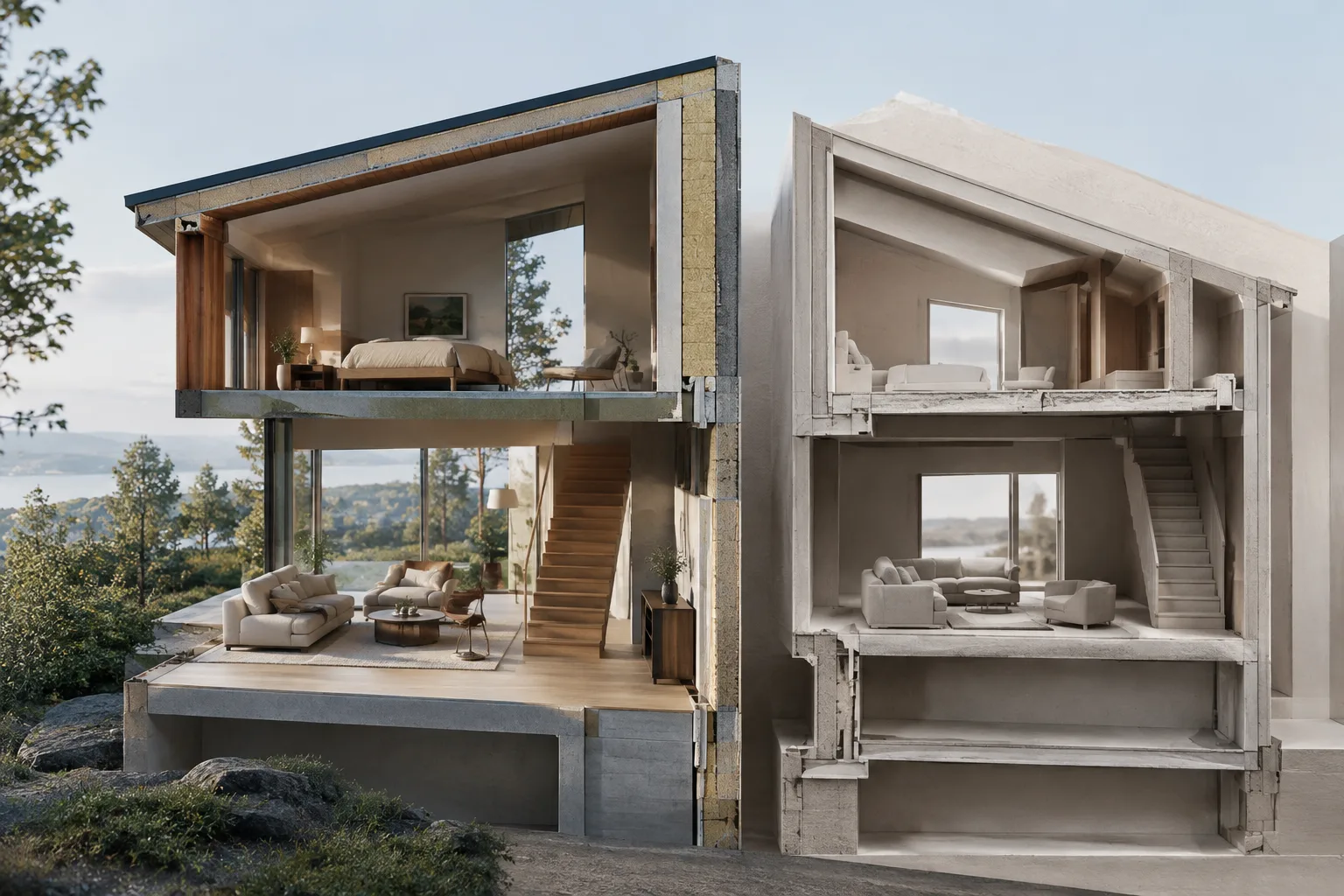
In Rhino 8, you can use the ClippingPlane, ClippingSections and ClippingDrawings commands to create a section view from an architectural model and turn it into a 2D drawing. Documented in McNeel’s Rhino 8 documentation, these tools offer ways to inspect different sections without deleting model geometry, save section views and create drawing output. This guide brings together the basic documented workflow and the points to check before delivery.
Choose a section plane and method
ClippingPlane creates a cutting plane that determines which part of the model is displayed in a viewport. By default, you can draw the rectangular plane by specifying two opposite corners. Other placement options are also available: Center uses a center point and a corner point, while Vertical places the plane perpendicular to the construction plane. AroundCurve creates a rectangle perpendicular to a selected curve, at a specified center along the curve. You can also draw the plane using three points or the midpoint of its first edge.
Use ClippingSections to create one or more sections relative to selected objects. You can select the objects to be clipped at the start of the command; after selecting them, press Enter to continue and create the section through all objects. If the widget appears red while placing it, the section plane may not intersect the overall world-coordinate bounding box of the relevant objects. Check the plane’s position before confirming it.
Direction, depth and label options
The Dir setting in ClippingSections selects the section direction. CPlane creates a section parallel to the current construction plane; X and Y use directions perpendicular to the plane and parallel to the corresponding axis. With Custom, you define the direction using two points. If the wrong side is being clipped, use Flip to switch which side is clipped and which remains unclipped.
The depth setting limits the portion that remains visible beyond the section plane. When CustomDepth is set to No in ClippingSections, the plane’s depth is infinite. Setting it to Yes enables the Depth option, where you can specify the visible thickness in model units. The documentation gives zero as the default Depth value; at zero, thin sections are drawn. In the ClippingPlane properties, enabling Custom Depth also reveals a depth point when control points are on. Move this point to change the distance.
| Setting | Documented value or option | Effect |
|---|---|---|
| CustomDepth | No | The section plane has infinite depth. |
| CustomDepth | Yes | Enables the Depth option so you can define the visible thickness. |
| Depth | Default: 0 | Sets the thickness of the visible portion; zero creates thin sections. |
| LabelMode | Default: Text | Displays the section name as text beside the direction indicators. |
You can enter a prefix under Name to label sections. For example, entering SEC numbers them SEC_01, SEC_02 and SEC_03. Under LabelMode, choose Text, Dot or None for the label display. The font and size of a Dot label cannot be controlled separately. With Text, the current annotation style’s font is applied; the text size depends on the widget size.
The Objects Clipped setting in ClippingPlane properties lets you manage the scope of the clipping operation by object or layer, independently of the viewport. All includes all objects; Include Selected includes only objects selected for custom clipping, while Exclude Selected includes all objects except those selected. Under Views Clipped, you can choose which viewports the clipping plane is active in. Reset Views disables the plane in all viewports.
Save a section view and turn it into a drawing
Run ClippingSections and select the objects to clip. To include all objects, press Enter after making your selection.
Set the direction with Dir. If needed, adjust CustomDepth and Depth, then place the plane in the viewport.
Enter a prefix for the sections under Name and choose the label format with LabelMode. SaveToNamedView saves the view corresponding to the section.
Sections placed in a perspective viewport create a Named View with perspective projection. If you need a parallel view, choose the placement viewport accordingly.
Run ClippingDrawings and select one or more section planes. Specify where to place the drawings; pressing Enter moves the current drawing’s base point to the World Top origin.
The 2D drawings generated with ClippingDrawings are projected onto the World XY plane. The program organizes the output by layers, allowing you to inspect it in the modeling and layout spaces. When you move a section plane, the position of its associated drawing is updated as well. However, if clipped objects or their properties change in the model, run UpdateClippingDrawings separately to recalculate the drawing. Deleting a clipping plane also removes its associated drawing and layers. Exploding drawing blocks with Explode breaks the link between drawing objects and the source geometry.
ClippingDrawings options determine the output’s content and appearance. ShowHatch controls hatch generation when the object’s section style is set to display a hatch; ShowSolid controls the creation of planar surfaces from sections through solid objects. AddBackground can project visible and hidden silhouette curves in front of the section plane into the drawing. This option does not add objects or layers excluded in the clipping plane properties to the background drawing. With AddBackground enabled, Projection lets you choose Parallel or Perspective. AddHidden controls hidden curves, while AddSilhouette controls silhouette curves. ShowLabel adds a label with the drawing name; LabelStyle sets the label to Dot or Text. ApplyToAll applies the current options to subsequent drawings.
Use in architectural and visualization workflows
Architects and interior designers can inspect the inside of a model with different section planes, save section views as Named Views and reopen them later. 2D drawing output helps bring sections and selected background geometry together in the same drawing workflow. Hatch, planar surface, hidden-line and label options can be adjusted to suit what the drawing needs to show.
In this workflow, it is particularly important to keep track of viewport selection and drawing freshness. The documentation notes that a saved section view created in a perspective viewport will also be in perspective. In addition, changes to objects or their properties do not automatically refresh the drawing. Before delivery, run the update command and check that objects or layers excluded by the clipping plane have not been included in the background drawing.
Common mistakes
Placing the plane without intersecting the relevant objects: check whether the widget appears red.
Expecting a depth limit without enabling CustomDepth: confirm that the Depth setting is available after selecting Yes.
Using an outdated 2D drawing after changing the model: run UpdateClippingDrawings.
Assuming that deleting a clipping plane removes only the plane: remember that its associated drawing and layers will also be deleted.
Expecting a Named View created in a perspective viewport to be parallel: take the viewport type used to place the section into account.
Sources
2 sourcesSource texts are not republished; short quotes are marked, everything else is our own summary and commentary.
Having tools for saving section views and generating 2D drawings within the same toolset in Rhino 8 can reduce repetitive work when moving from model to drawing. Offices that save different sections as Named Views can reuse the same views throughout a project.
In practice, the most important check is whether the drawing is up to date: changes to objects or their properties require an additional update. It is useful for offices in Turkey to add this step to their delivery checklist and account for the fact that deleting a clipping plane also removes its associated drawings. The documentation does not specify any special hardware or licensing requirements for these features.
Frequently asked questions
How do you create a section from a model in Rhino 8?
Use ClippingSections to select objects, set the direction and, if needed, the depth, then place the section plane in the viewport. You can save the corresponding view with SaveToNamedView.
Does a Rhino ClippingDrawings drawing update when the model changes?
When you move the section plane, the associated drawing updates. If clipped objects or their properties change, you need to run UpdateClippingDrawings.
How do you limit section depth in Rhino?
In ClippingSections, set CustomDepth to Yes to enable Depth, then specify the thickness in model units. You can also adjust the depth by moving the depth point while control points are visible in the ClippingPlane properties.