In brief
- A camera motion solve requires at least eight common tracks across two selected keyframes, along with noticeable parallax.
- Track > Detect Features finds feature points in the current frame and places tracking markers.
- After solving, you can set the floor, scene origin, and X/Y axes to orient the scene.
- Planar surface tracking requires at least four common tracks and can be used to place an image on a surface.
What you’ll learn in this guide
Camera tracking architectural footage in Blender is one way to connect the movement in real-world footage to a 3D scene. In this workflow, distinctive points in the image are tracked across frames, and then the camera or object motion is solved. The resulting solve can be applied to 3D elements created in Blender or imported into it. Tracking data can also be used to track planar surfaces and support compositing.
The steps below are based on the tracking tools described in the Blender user manual. The result depends on the quality of the tracks in the footage, the camera motion, and accurate initial values. Tracking a single flat surface and solving a camera’s 3D motion address different needs, so choose the appropriate method for your footage and goal.
Requirements and getting started
You’ll need a video clip with trackable visual features and Blender. The source guide is the current online manual; it does not specify a particular Blender version or account requirement. Values such as camera focal length and lens distortion can affect the accuracy of the camera solve. According to the manual, focal length can be read automatically from camera settings or EXIF data; if the initial values are completely wrong, you should not expect the solver to find the correct values.
Parallax—the relative movement of elements at different depths in the shot—is important for camera solving. If the camera only rotates without changing position, you can use Tripod Motion. This specialized solve calculates relative camera rotation rather than determining true 3D depth. Planar tracking, by contrast, is useful when you want to place another image on a surface in the footage, such as a screen, sign, or panel.
Step-by-step camera tracking
Prepare the clip in the tracking view. Switch to Tracking Mode in the Movie Clip Editor. In this workspace, you can track the clip and markers, as well as switch between different display options. Make sure the points you track are visually distinct, and check that they belong to architectural elements in the scene.
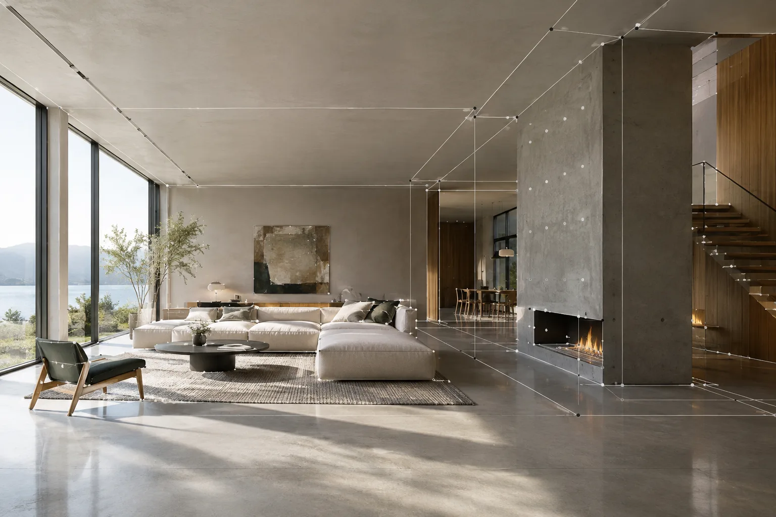
Create tracking points. To find markers in the current frame, use Track > Detect Features. This operation evaluates features only in the current frame; it can also select points on moving objects, so check that each marker belongs to a part of the scene that is stationary relative to the camera. Markers too close to the image edge may fail quickly, so you can set an edge margin with the Margin setting. The Threshold and Distance values affect how many markers are found and how close they are to one another.
Track forward and backward. Use the forward or backward options in the Track Motion command to track selected markers through the sequence. The manual lists Ctrl-T for tracking forward and Shift-Ctrl-T for tracking backward. Watch the markers as they track to make sure they follow the same feature on the surface. If a track slips, stopping and correcting that point can help prevent the error from carrying over to subsequent frames.
Solve the camera motion. Set the starting and ending keyframes in the Solve panel. According to the Blender manual, the two selected keyframes must have at least eight common tracks, with noticeable parallax between them. When the solve succeeds, Blender reports the average reprojection error. This value indicates how far the reconstructed 3D tracking points deviate from their original positions when projected back into the image. The manual describes values below 0.3 as accurate, and values in the 0.3–3.0 range as usable and reasonably good. If the value is above 3, review the tracks, focal length, and distortion coefficients.
Clean up bad tracks. Clean Tracks can select, delete, or remove problematic portions of tracks based on specified track-length and reprojection-error conditions. Short tracks and tracks with high errors can reduce solve quality. If a track is only bad in part of the shot, consider removing the bad segments rather than deleting the whole track.
Set the scene orientation and scale. After solving, you can set the floor, origin, and X/Y axes to make the real scene more useful in 3D. If you know a real-world distance, use Set Scale or Apply Scale to adjust the scene scale. This step helps 3D elements match the footage not only in movement, but also in scene orientation.
Planar surface tracking and tripod shots
Planar tracking may be appropriate if your goal is to place an image on a wall, screen, or sign in the footage. First, track features on the same plane; according to the manual, at least four of these tracks must be tracked throughout the shot to create a plane track. Each pair of frames must have at least four common tracks. The tracks do not have to be at the corners of the surface; if the corners are occluded, other tracks on the same plane can be used. The resulting plane track can be applied to the image in the compositing stage with the Plane Track Deform node.
If the camera rotates without changing position, consider the Tripod Motion option. This differs from a standard camera solve: instead of determining depth, it solves relative rotation and projects the tracks onto a sphere equidistant from the camera. The manual notes that this specialized solve can generally use 5–10 tracks per frame; more tracks do not always mean a more accurate result.
Common mistakes
Treating moving objects as stationary scene points: Because feature detection does not consider other frames, markers can land on moving elements. Check the tracks you plan to use in the solve.
Ignoring the parallax requirement: Camera motion solving requires noticeable parallax between two keyframes. If the camera only rotates without changing position, consider Tripod Motion. Use planar tracking if you want to track the movement of a single surface or place content on it.
Leaving lens values at arbitrary settings: If the initial estimates for focal length and distortion are far off, the refinement process may not find the right result. First check the known camera values and shot information.
Continuing without reviewing the solve error: A high reprojection error may indicate that the tracks are not accurate enough or that the camera parameters are incorrect. Clean up problematic tracks and check the solve again.
What does this offer architectural and visualization workflows?
This technique can be useful for visualization teams looking to place 3D elements over existing architectural video or add new content to a flat surface. In architectural and interior projects, solving the camera motion provides a basis for making designed elements move with the footage. However, the sources do not specify a particular render, export, or project delivery method, so target software and file compatibility should be checked separately as part of the workflow.
The sources do not describe specific requirements for footage, hardware, or licensing. In practice, prioritize stable tracks, accurate camera information, and choosing the right type of solve. For offices, testing the results on different footage examples and correcting tracks before adding 3D content when reprojection error is high can make the process more controlled.
Next steps
After the camera solve, check the scene orientation and scale, then experiment with how 3D elements can be linked to the motion data. If your goal is to replace content on a single surface, explore the planar tracking tools. For handheld footage with camera shake, look at Blender’s 2D Stabilization feature. If features disappear between frames, you can manually position a marker on the track where it reappears, then run Refine Markers.
Sources and license
This tutorial is adapted from the Motion Tracking introduction, track editing, tracking settings, and solving tools sections of Blender’s official online manual. The sources are licensed under CC BY-SA 4.0; the content has been translated and adapted into Turkish.
Sources
3 sourcesSource texts are not republished; short quotes are marked, everything else is our own summary and commentary.
For architecture offices and visualization teams in Turkey, Blender tracking can support workflows that add 3D design elements to existing footage or replace content on a planar surface. The biggest practical benefit comes from choosing the right solve method for the footage and cleaning up tracks in a controlled way.
That said, this guide does not provide information about hardware requirements, licensing terms, or compatibility between software, so these should be verified separately before a project begins. For students, experimenting with the relationship between tracks, camera solving, and scene orientation can be instructive. In offices, reviewing tracking data before moving on to 3D content production can save time when footage produces a high reprojection error.
Frequently asked questions
How many tracking points are needed to solve camera motion in Blender?
According to the Blender manual, the two selected keyframes need at least eight common tracking points, with noticeable parallax between them.
How do you use planar tracking in Blender?
You can create a plane track by tracking at least four tracks on the same surface. In compositing, the track can be used to project an image with the Plane Track Deform node.
What does a high reprojection error mean in Blender camera tracking?
According to the manual, values above 3 may mean that some tracks need to be tracked more accurately, or that the focal length and distortion coefficients need to be checked.