In brief
- ShrinkWrap works with NURBS surfaces, SubDs, meshes, point clouds, and point objects.
- Target edge length, offset, smoothing, and polygon optimization affect the resulting mesh.
- The option to fill holes in input objects may also close small intentional gaps, so use it with care.
- The Check command can report problems in an object’s data structure; passing the check does not prove the model is flawless in every respect.
What will you learn in this guide?
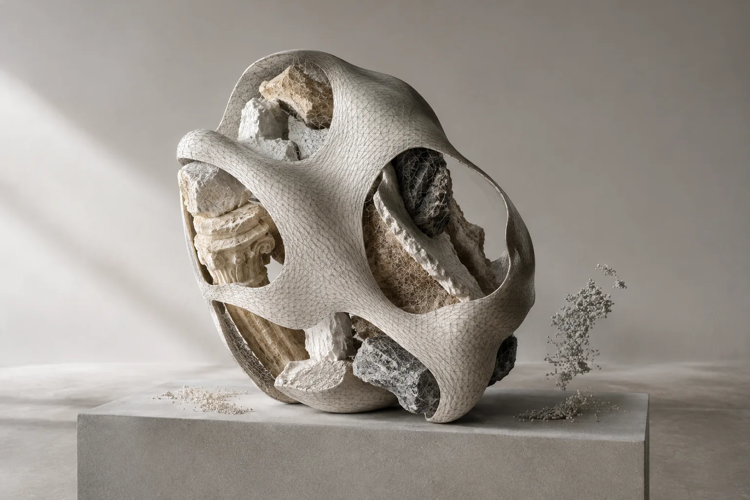
ShrinkWrap in Rhino 8 creates a new mesh around selected geometry. McNeel’s help documentation describes the command for uses such as creating meshes for 3D printing, enclosing multiple inputs in a single mesh, generating meshes from scan data, and creating closed meshes around geometry that is difficult to repair.
This guide covers the supported input types, how the main options affect the result, and ways to inspect the mesh you create. There is no single combination of settings that works for every model. That makes it important to compare changes using the preview and review the result for its intended use.
Requirements and preparation
This guide is based on McNeel’s Rhino 8 help documentation for the ShrinkWrap, Mesh, and Check commands. The sources do not specify an account type, plug-in, hardware requirement, or pricing information. ShrinkWrap accepts NURBS surfaces, SubDs, meshes, point clouds, and point objects as inputs.
Before starting, decide which geometry should be included in the result. Since there is an option to delete input objects, check its state before processing if you need to preserve the source geometry. The documentation states that this option deletes input objects only if the output mesh is created successfully.
Creating a mesh with ShrinkWrap
Select the inputs and define your goal. Choose the supported objects you want to include in the enclosing mesh. You might want a single result around multiple objects, or a mesh that encompasses scan fragments. Consider which details of the model are important to preserve at this stage; this will help guide your assessment of the settings that follow.
Run the command and enable the preview. ShrinkWrap’s Preview option lets you view the result mesh during the command session. You can also display the preview mesh’s wires and hide input objects while previewing. Before accepting the result, inspect its overall shape and how it encloses the inputs.
Assess the target edge length. This option sets an approximate target length for edges in the output mesh; Rhino calculates the default automatically. Increasing polygon optimization can cause edge lengths to deviate further from the specified target. Since the source documentation does not recommend a specific value for every model, use the preview to assess the required detail alongside mesh density.
Adjust the position of the enclosing surface with Offset. Offset is entered in model units. A positive value pushes the mesh farther out around the input geometry, resulting in more faces; a negative value moves the mesh inward and reduces the face count. Compare different values in the preview. Also keep in mind that Offset has a limited effect on target edge length.
Test smoothing and polygon optimization separately. Setting the smoothing iteration value to zero turns smoothing off. A higher value can simplify the mesh further while also changing its shape inward. Polygon optimization is set from 0 to 100; as the value increases, the face count decreases further, while sharp edges are preserved. Change one setting at a time and compare the preview, then test the other, to see how each affects the shape.
Review the relevant option for point and vertex inputs. “Inflate Vertices and Points” builds the output mesh from mesh vertices or point cloud points. For NURBS surfaces and SubDs, it uses render mesh vertices; customizing the render mesh settings for these objects may be useful if you need more vertices. The option is on by default for point and point cloud inputs, and off for other object types. When the resulting meshes intersect, they may merge into larger meshes. A negative offset pulls the mesh produced by this option toward the source vertices or points.
Check hole filling and color transfer. “Fill holes in input objects” fills holes in input objects before the mesh is created. If small gaps are part of the design, this may produce an unwanted result; inspect the preview with this in mind. The option has no effect for point or point cloud inputs, or when “Inflate Vertices and Points” is on. “Compute vertex colors” adds mesh vertex colors and point cloud display colors to the resulting mesh.
Review the sources and result one last time. If “Delete input objects” is enabled, the input objects are deleted when the result mesh is created successfully. Decide beforehand whether you need to preserve the source geometry. Check the shape and any areas expected to be closed in the preview, then assess whether the mesh is suitable for its intended workflow.
How to check the mesh and geometry
Rhino’s Mesh command can also create meshes, but it should not be considered the same operation as ShrinkWrap. Mesh creates a mesh from a NURBS surface, polysurface, or SubD. According to Rhino’s documentation, a mesh created from a solid object has no holes; this can be useful when exporting to STL files for rapid prototyping. Meshes created with the Mesh command are described as separate from, and editable independently of, the objects they were generated from. This information should not be generalized to the characteristics of ShrinkWrap output.
If you suspect an error in the data structure of a selected object, the Check command generates a report. However, passing the Check command does not mean an object is flawless in every respect: some issues, such as self-intersecting or folded-back surfaces, can be difficult to detect automatically.
For mesh diagnostics, ShowEdges can be used to find naked edges. The documentation also lists different tools for conditions such as duplicate faces, zero-length edges, and disconnected pieces. Treat these as separate steps for inspecting and troubleshooting the result mesh, not as ShrinkWrap settings.
Common mistakes
Increasing optimization without checking the shape: Reducing the face count can affect mesh details. Preserving sharp edges does not mean every small detail will remain unchanged.
Confusing Offset with target edge length: These options have different effects. You can compare the result more easily by changing one while keeping the other fixed.
Assuming hole filling is always appropriate: Some small gaps may be intentional. Keep this possibility in mind when using the automatic fill option.
Treating a Check result as a definitive quality approval: Check reports errors in an object’s data structure; it does not guarantee that it will find every geometric issue.
Overlooking the option to delete input objects: If you need to keep the source geometry, check this setting before processing.
Impact on architecture and visualization workflows
Architects, interior designers, and visualization teams may find ShrinkWrap useful, particularly when they need a mesh that encloses 3D scan fragments or multiple objects. McNeel also associates the command with uses such as 3D printing, reverse engineering, shell operations, and creating meshes around geometry that is difficult to repair.
The face count and shape of the mesh are affected by the selected options. Review the result according to its intended use; ShrinkWrap should not be treated as an automatic solution for every mesh creation need. The Mesh command also has density and quality settings for creating meshes from NURBS surfaces. Since the sources provide no information about pricing, hardware requirements, or compatibility with other software, verify these separately before starting a project.
Next steps
Start with a sample geometry and change the target edge length, offset, smoothing, and polygon optimization one at a time. Comparing the preview for each test makes it easier to understand how each option affects the mesh. Then assess hole filling, using vertices and points, color transfer, and deleting input objects according to the needs of your work.
If you suspect the result has naked edges or another mesh issue, use Rhino’s diagnostic tools. You can use the Check command for a structural check, but remember that it does not detect every possible model issue.
Sources and licensing
This guide is adapted into Turkish based on McNeel’s official Rhino 8 help documentation for the ShrinkWrap, Mesh, and Check commands. The source records describe the documents as “free”; since they do not specify a particular license name, no more specific license type is claimed.
Sources
3 sourcesSource texts are not republished; short quotes are marked, everything else is our own summary and commentary.
ShrinkWrap can be a useful mesh creation step for architecture and visualization teams working with scan data or multiple pieces of geometry. It can make a practical contribution to the workflow when a single result is needed around different inputs, especially if you test the options using the preview. Still, since face reduction and smoothing can change the result, do not assess the mesh solely by whether it is closed.
For offices and students in Turkey, licensing costs, hardware needs, and compatibility with other software in use should be checked separately before making a decision; the sources provide no information on these topics. Testing the result and its suitability for project requirements on a small sample file first is a cautious way to begin.
Frequently asked questions
What types of geometry does Rhino 8 ShrinkWrap work with?
NURBS surfaces, SubDs, meshes, point clouds, and point objects can be used as inputs.
Can ShrinkWrap create a closed mesh?
McNeel lists creating a valid closed mesh for broken or difficult-to-repair geometry among the command’s uses. Preview and inspect the result according to your needs.
Does Rhino’s Check command show that a model is completely error-free?
No. Check reports errors in an object’s data structure; passing the check does not prove that every possible geometric issue has been found and resolved.